Texas InstrumentsUnited States

DC DC CONVERTER 0.8-3.6V
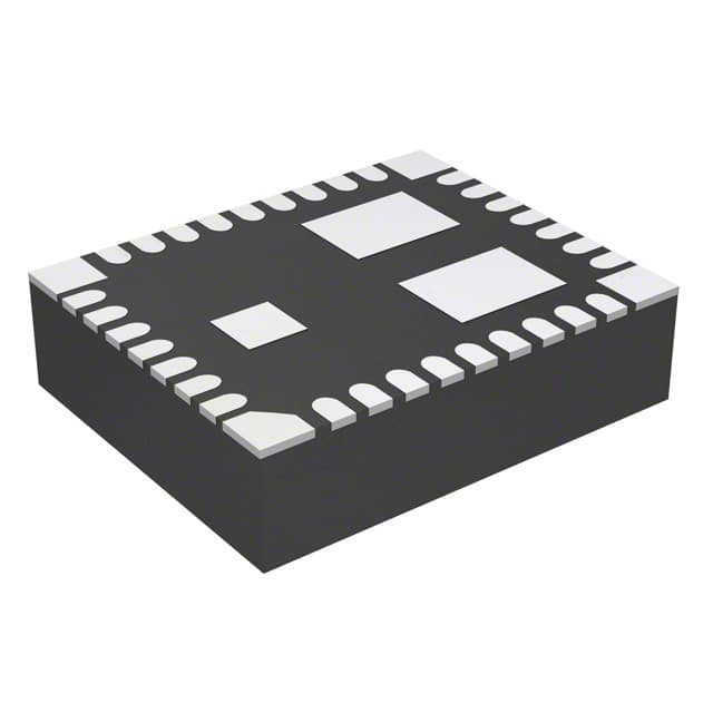
TPS84610RKGT is a 2.95V to 6V input, 6A output synchronous buck integrated power solution in a 9x11x2.8 mm BQFN package, operating from -40°C to 85°C with up to 96% efficiency.Checked against the datasheet
All alternatives
View full reportTechnical parameters
Key specs
Input voltage2.95 ~ 6 V
Output voltage800 mV ~ 3.6 V
Output current6 AMax
IsolationNon-isolated
Datasheet-verified parameters
29 items| Parameter | Value and test conditions | Source |
|---|---|---|
| Input Voltage Range | 2.95-V to 6-V | |
| Output Voltage | 0.8 V to 3.6 V | |
| Output Current | 6-A | |
| Package | 9×11×2.8 mm BQFN | |
| Operating Temperature Range | –40°C to 85°C | |
| RoHS | Exempt |
All parameters (22)
| Power | |
|---|---|
| Current - Output (Max) | 6A |
| Voltage - Input (Max) | 6V |
| Voltage - Input (Min) | 2.95V |
| Voltage - Output 1 | 0.8 ~ 3.6V |
| Voltage - Output 2 | - |
| Voltage - Output 3 | - |
| Environment and package | |
| Mounting Type | Surface Mount |
| Operating Temperature | -40°C~85°C |
| Package | Tape & Reel (TR); Cut Tape (CT); Digi-Reel® |
| Package / Case | 39-BQFN Exposed Pad |
| Size / Dimension | 0.43" L x 0.35" W x 0.11" H (11.0mm x 9.0mm x 2.8mm) |
| Supplier Device Package | 39-B1QFN (11x9) |
| Other | |
| Applications | ITE (Commercial) |
| Base Product Number | TPS84610 |
| Control Features | Enable, Active High |
| Efficiency | 96% |
| Features | UVLO |
| Mfr | Texas Instruments |
| Number of Outputs | 1 |
| Product Status | Active |
| Series | - |
| Type | Non-Isolated PoL Module |
Pinout and package
RKG PACAKGE 39 PINS (TOP VIEW)
| Pin | Name | Function | Source |
|---|---|---|---|
| 1 | AGND: Zero VDC reference for the analog control circuitry. Should be connected directly to the PCB analog ground plane. | ||
| 2 | DNC: Do Not Connect. Do not connect these pins to AGND, to another DNC pin, or to any other voltage. | ||
| 3 | DNC: Do Not Connect. Do not connect these pins to AGND, to another DNC pin, or to any other voltage. | ||
| 4 | RT/CLK: Automatically selects between RT mode and CLK mode. An external timing resistor adjusts the switching frequency. In CLK mode, the device synchronizes to an external clock. | ||
| 5 | AGND: Zero VDC reference for the analog control circuitry. Should be connected directly to the PCB analog ground plane. | ||
| 6 | SS/TR: Slow-start and tracking pin. Connecting an external capacitor adjusts the output voltage rise time. A voltage applied allows for tracking and sequencing control. | ||
| 7 | STSEL: Slow-start or track feature select. Connect to AGND to enable internal SS capacitor (~1.1 ms). Leave open to enable TR feature. | ||
| 8 | VOUT: Output voltage. Connect output capacitors between these pins and the PGND plane, close to the device. | ||
| 9 | VOUT: Output voltage. Connect output capacitors between these pins and the PGND plane, close to the device. | ||
| 10 | VOUT: Output voltage. Connect output capacitors between these pins and the PGND plane, close to the device. | ||
| 11 | VOUT: Output voltage. Connect output capacitors between these pins and the PGND plane, close to the device. | ||
| 12 | VOUT: Output voltage. Connect output capacitors between these pins and the PGND plane, close to the device. | ||
| 13 | VOUT: Output voltage. Connect output capacitors between these pins and the PGND plane, close to the device. | ||
| 14 | VOUT: Output voltage. Connect output capacitors between these pins and the PGND plane, close to the device. | ||
| 15 | DNC: Do Not Connect. Do not connect these pins to AGND, to another DNC pin, or to any other voltage. | ||
| 16 | DNC: Do Not Connect. Do not connect these pins to AGND, to another DNC pin, or to any other voltage. | ||
| 17 | PH: Phase switch node. Should be connected by a small copper island under the device for thermal relief. Do not connect any external component. | ||
| 18 | PH: Phase switch node. Should be connected by a small copper island under the device for thermal relief. Do not connect any external component. | ||
| 19 | PH: Phase switch node. Should be connected by a small copper island under the device for thermal relief. Do not connect any external component. | ||
| 20 | PH: Phase switch node. Should be connected by a small copper island under the device for thermal relief. Do not connect any external component. | ||
| 21 | PH: Phase switch node. Should be connected by a small copper island under the device for thermal relief. Do not connect any external component. | ||
| 22 | PH: Phase switch node. Should be connected by a small copper island under the device for thermal relief. Do not connect any external component. | ||
| 23 | PH: Phase switch node. Should be connected by a small copper island under the device for thermal relief. Do not connect any external component. | ||
| 24 | PH: Phase switch node. Should be connected by a small copper island under the device for thermal relief. Do not connect any external component. | ||
| 25 | PH: Phase switch node. Should be connected by a small copper island under the device for thermal relief. Do not connect any external component. | ||
| 26 | DNC: Do Not Connect. Do not connect these pins to AGND, to another DNC pin, or to any other voltage. | ||
| 27 | PWRGD: Power good fault pin. Asserts low if the output voltage is out of tolerance. A pull-up resistor is required. | ||
| 28 | INH/UVLO: Inhibit and UVLO adjust pin. Use open drain or open collector logic to control INH. A resistor between this pin and AGND adjusts UVLO voltage. | ||
| 29 | AGND: Zero VDC reference for the analog control circuitry. Should be connected directly to the PCB analog ground plane. | ||
| 30 | VIN: Positive input voltage power pins, referenced to PGND. Connect external input capacitance between these pins and the PGND plane, close to the device. | ||
| 31 | VIN: Positive input voltage power pins, referenced to PGND. Connect external input capacitance between these pins and the PGND plane, close to the device. | ||
| 32 | VIN: Positive input voltage power pins, referenced to PGND. Connect external input capacitance between these pins and the PGND plane, close to the device. | ||
| 33 | AGND: Zero VDC reference for the analog control circuitry. Should be connected directly to the PCB analog ground plane. | ||
| 34 | AGND: Zero VDC reference for the analog control circuitry. Should be connected directly to the PCB analog ground plane. | ||
| 35 | VADJ: Connecting a resistor between this pin and AGND sets the output voltage above the 0.8V default voltage. | ||
| 36 | SENSE+: Remote sense connection. Connect this pin to VOUT at the load for improved regulation. | ||
| 37 | PowerPAD (PGND): Provides both an electrical and thermal connection to the PCB. Should be connected directly to the PCB power ground plane using multiple vias. | ||
| 38 | VOUT: Output voltage. Connect output capacitors between these pins and the PGND plane, close to the device. | ||
| 39 | PH: Phase switch node. Should be connected by a small copper island under the device for thermal relief. Do not connect any external component. |
Documents
Datasheet-verified content is extracted by AI from the manufacturer datasheet. Click a page number to view the original.