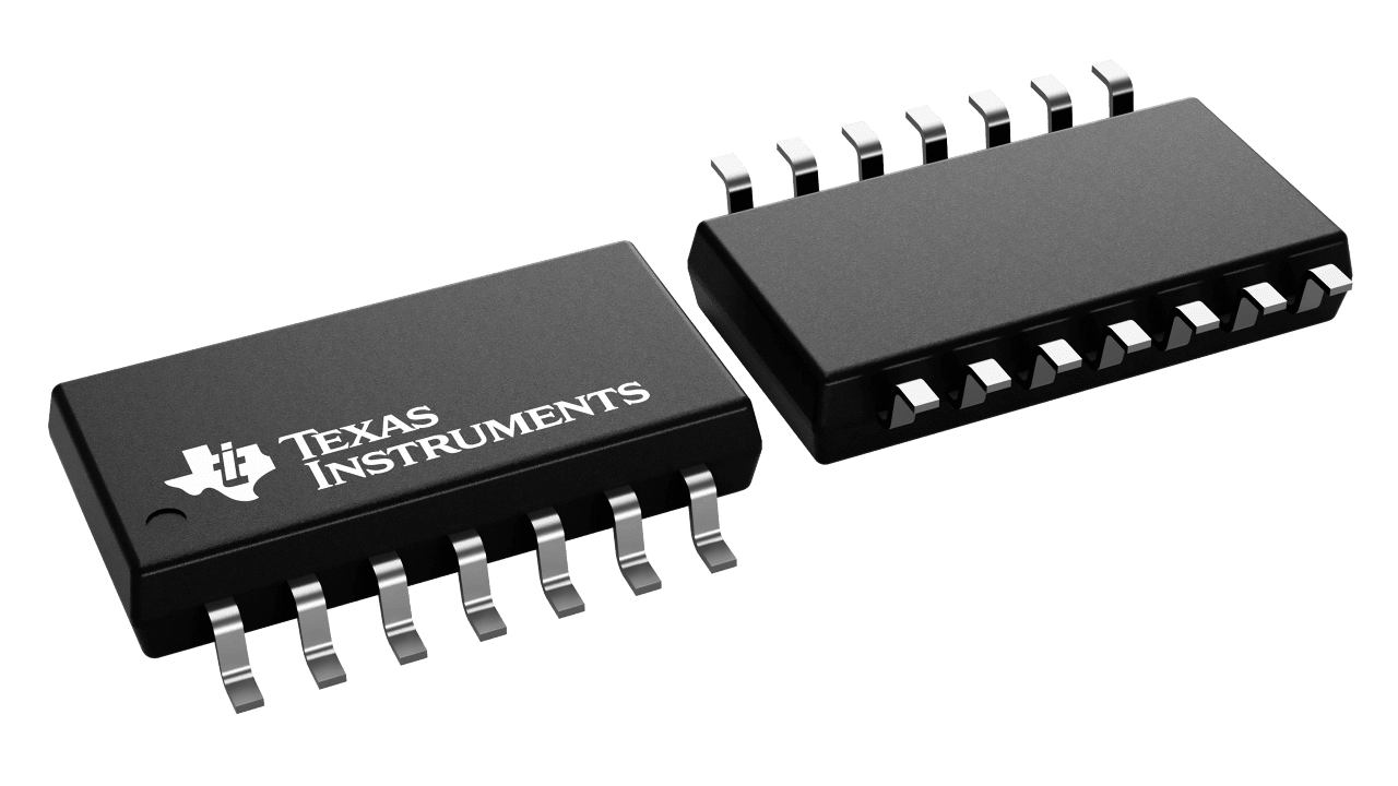

CD4541B programmable timer consists of a 16-stage binary counter, an oscillator that is controlled by external R-C components (2 resistors and a capacitor), an automatic power-on reset circuit, and output control logic. The counter increments on positive-edge clock transitions and can also be reset via the MASTER RESET input. The output from this timer is the Q or Q\ output from the 8th, 10th, 13th, or 16th counter stage. The desired stage is chosen using time-select inputs A and B (see Frequency Select Table). The output is available in either of two modes selectable via the MODE input, pin 10 (see Truth Table). When this MODE input is a logic "1", the output will be a continuous square wave having a frequency equal to the oscillator frequency divided by 2 N . With the MODE input set to logic "0" and after a MASTER RESET is initiated, the output (assuming Q output has been selected) changes from a low to a high state after 2 N-1 counts and remains in that state until another MASTER RESET pulse is applied or the MODE input is set to a logic "1". Timing is initialized by setting the AUTO RESET input (pin 5) to logic "0" and turning power on. If pin 5 is set to logic "1", the AUTO RESET circuit is disabled and counting will not start until after a positive MASTER RESET pulse is applied and returns to a low level. The AUTO RESET consumes an appreciable amount of power and should not be used if low-power operation is desired. For reliable automatic power-on reset, V DD should be greater than 5V. The RC oscillator, shown in Figure 2, oscillates with a frequency determined by the RC network and is calculated using: Where f is between 1kHz and 100kHz and R S and 2R TC .
All alternatives
View full reportTechnical parameters
| Environment and package | |
|---|---|
| Operating temperature range (°C) | -55 to 125 |
| Other | |
| Bits (#) | 1 |
| Rating | Catalog |
| Technology family | CD4000 |